![]()
- HOME
- Product info
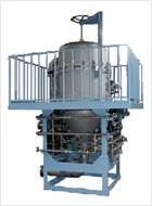
- TYPE-UF TUBULAR FILTER
PRODUCTSTYPE-UF TUBULAR FILTER
Filter equipment to remove surface coating chemical sludge
Filter equipment suited for aluminum co-diffusion coating chemical liquid.
This equipment cyclically filters the entire quantity of chemical liquid in the tank, and can almost completely remove aluminum particles that conventional settling sedimentation systems find difficult to remove.
This equipment thus enables the stable maintenance of high SS control values.
Equipment features
- This equipment uses a special filter cloth mounted on a cylindrical stainless steel filter medium without using D.E. powder. As a result, this equipment always offers high filtration accuracy in a stable manner
- The counterpressure flashing system can wash the filter cloth efficiently in a very short time. Clogging on the filter cloth due to long-term equipment service can be removed by washing with nitric acid.
- Backwash drain liquid is automatically dewatered by the EXCELER FILTER, and its solid contents are discharged as solid dewatered cake. Almost all filtrate is recovered here and there is no loss of chemical liquid.
- The filter equipment is constructed to maximize the effective filtration area. This increases the filtration capacity and enables the filtration of a large amount of raw liquid.
- This filtration system features a simple flow of liquid and easy operation, and is thus suited for automation.
Operation
- General View
- 1.Filtration Procces
- 2.Backwash Procces
① TUBULAR FILTER ② Drain Tank ③ EXCELER FILTER ④ Air Tank ⑤ Nitric acid Tank ⑥ Phosphate Tank ⑦ Filter Pump ⑧ Sludge Pump ⑨Nitric acid Pump ⑩ Cushion Tank
The chemical liquid sent from the chemical tank by the filtration pump enters the filter body through a raw liquid inlet on the lower part of the tubular filter, is filtered by the special filter cloth mounted on the cylindrical stainless steel filter medium, and then returns to the chemical tank through the filtrate outlet on the upper part.
As filtration continues for a few hours, chemical sludge in the raw liquid is captured by the filter paper and deposited there.
This deposition increases pressure in the filter equipment, while simultaneously reducing the flow rate.
At this time, the filtration process ends and the next backwash process begins.
At the end of the filtration process, all automatic valves at the raw liquid inlet and the filtrate outlet close, and the filtration pump stops.
The backwash air valve then opens to jet compressed air into the filter body.
The compressed air expels filtration liquid on top of the filter via blasts from the inside to outside of the filter cloth, in order to wash it. The counterpressure flashing system completes washing in a few minutes.
This backwash liquid is stored temporarily in the drain tank and dewatered by the EXCELER FILTER.
This filtrate is recovered in the chemical tank, with dewatered sludge being discharged to the outside.
Immediately after backwashing ends, the filtration process restarts.
Use
- Coating industries…
After this filter equipment removes sludge from pre-painting chemical liquid, the SS value of the filtrate remains stably constant at 20 ppm or less.
Accordingly, it is possible to maintain the SS value of liquid in the tank within the range of 100 to 200 ppm by cyclically filtering the entire quantity of chemical liquid in the chemical tank.
In particular, SS generated by the chemical processing of aluminum material is low in specific gravity and very fine.
This is why SS is difficult to remove via the filtration by conventional continuous settling systems.
However, this filter equipment can maintain a very low SS value without any problem.
Major items
| TYPE | UF-55S | UF-65S | UF-75S | UF-90S | UF-105S | UF-120S |
|---|---|---|---|---|---|---|
| TUBULAR FILTER Filtration area(m2) |
2.4 | 3.6 | 5.0 | 7.2 | 10.0 | 14.0 |
| A(㎜) | 1600 | 1800 | 2000 | 2000 | 2200 | 2200 |
| B(㎜) | 3300 | 3700 | 4000 | 4200 | 4600 | 4800 |
| C(㎜) | 710 | 710 | 910 | 910 | 910 | 1820 |
| D(㎜) | 5400 | 5800 | 6300 | 6500 | 6900 | 8000 |
| E(㎜) | 3500 | 3800 | 3900 | 4100 | 4400 | 4700 |
| F(㎜) | 1970 | 1970 | 2150 | 2150 | 2150 | 2150 |
| AIR TANK(L) | 600 | 800 | 1000 | 1200 | 1200 | 2000 |
| Inlet and outlet bores | 50A | 50A | 65A | 65A | 80A | 100A |
| Filtering capacity(m3/Hr) | ~12 | ~16 | ~25 | ~35 | ~50 | ~70 |
1) The filtration capacity is not shown here as it depends on the liquid specifications.
2) The required compressed air is 0.45 MPa minimum and 0.2Nm3/min. (ANR).
3)The wetted portions of the equipment are made of SUS304 as standard.
(The portions excluding the filter medium can also be made of SUS316.)